
Safety light curtain with no 3rd box or controller. Pylons are rated Nema 4 (IP 65) and has two monitored solid state PNP outputs. Mechanical captive contact (dry) safety relays also available. Input power is 24VDC. Complete system diagnostics, mounting brackets and connection cables are supplied standard. Type 4 / Category 4. Made in USA.
 The Model SS is an infrared safety light curtain that is designed to the IEC 61496 standard. When properly installed, it protects the machine operator by passing an invisible infrared light beam across an area to be guarded and examining whether or not the light beam(s) are blocked. If the light beam(s) are blocked, monitored solid state outputs will open, issuing a “STOP” command to the machines normally closed (N.C.) “STOP” circuit.
The System is composed of a transmitting unit (EMITTER), and a receiving unit (RECEIVER). The entire system is control reliable Category 4 (per IEC 61496). A single fault anywhere within the Model SS will not prevent at least one of the solid state outputs from opening up, (allowing a “STOP” command) when either a beam is broken or an internal fault occurs.
Theory of operation.
The Model SS protects an area by projecting a curtain of infrared light. The infrared emitters and receivers face each other across the field to be protected. Each emitter/receiver pair is spaced along the length of the pylons at regular intervals from .5”, up to 8” depending on the application. The smaller spacing are for finger guarding, the larger spacing are for body protection.
The emitter/receiver pairs are scanned sequentially (one at a time) by a very short pulse of infrared light starting from bottom (cable end), and working up to the top, until every beam pair has been scanned. Two 16 bit computers in the emitter pylon and two 16 bit computers in the receiver pylon control the operation, as well as cross check each pylon.
The System.
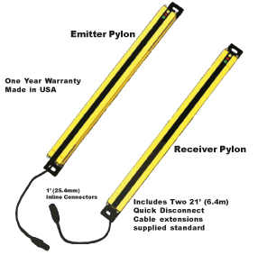
The Model SS employs infrared technology in a small sealed NEMA 4 aluminum housing with an infrared passing (daylight filtering) acrylic lens. This system provides harmless invisible protection and an unobstructed view of the guarded area. There are two parts to the Model SS: An Emitter pylon and a Receiver pylon. The Emitter pylon has no outputs, but does contain a digital CAN data network to allow it to be linked to the Receiver pylon (although not required for operation). The Receiver pylon contains the digital CAN data network and two monitored solid state 24vdc outputs.
Both pylons are synchronized to each other either via the CAN data network or electronically.
System Safety.
The Model SS incorporates redundant, and diverse technology that provides a backup for every system that could cause an unsafe condition.
External Device Monitoring (EDM).
A method in which the Model SS Category 4 safety light curtain logic monitors the state of various external control devices. The control devices are external and not part of the Model SS light curtain pylons. A lockout or stop signal will result if an unsafe state is detected in an external device.
The External Device Monitoring (EDM) is an optional function of the Model SS safety light curtain for monitoring the status of external devices such as gate and door switches, safety switches or the main control element of the drive (MPCE).
Solid state outputs are turned on separately to be checked and assure neither output has been shorted, before fully turning on.
Design Criteria:
–Designed to meet IEC 61496-1 & 2, UL 1998, UL subject 491, OSHA, ANSI, CSA, ANSI-RIA R15.06-2012
–Safety Category 4 (EN 954-1 and IEC 61496 Part 1 and Part 2 or EN 61496)
–SIL 3 (EN 61508)
–Performance Level PL e (ISO 13849-1)
–Microprocessor redundancy for both Emitter and Receiver pylons
–Redundant, monitored, 24vdc solid state outputs (PNP)
–Watchdogs on CPU’s and outputs prevent unintentional output during lockups.
Digital CAN Data Network.
Twisted pair data network allow the Receiver pylon to communicate to a remote operating device as well as the Emitter pylon. The pylon status will be displayed on both pylons.
The optional Remote Status Display (RSD) may be used in conjunction with the Model SS Safety Light Curtain. The RSD provides the machine operator and front line supervisor immediate system status and diagnostics when the Model SS is mounted inside the machine control panel. The RSD also controls all blanking options directly from the panel location where it is installed.
• Customized Blanking Available
 Remote Status Display (RSD) Components:
• Red/Green/Yellow indicator lights
• Diagnostic scrolling message display with 5’ (1.5m) of connector cable
• Keyed selector switch and yellow blanking active indicator supplied if blanking is used
The RSD components are mounted on a steel plate and are designed to be exterior panel mounted. The RSD option enhances safety and is a time saver at machine set-up and when maintenance diagnostics are required.
Cincinnati Interface
Description: The Cincinnati Interface is provided to allow an external device to determine if the light curtain is still capable of shutting down the safety control circuit. The Cincinnati Interface allows an external device to override the light curtain and initiate a RED condition and open up the standard output relay contacts.
Application: Cincinnati Press, PLC
• Manual Latching Relay Provision
 Floating Blank – (8K) Option
The “Floating Blank” option provides the flexibility necessary to effectively guard all types of equipment that require multiple floating beams. This is quite common in the fabricating industry where the work piece moves.
The “Floating Blank” permits work pieces to be formed vertically or horizontally through the guarded area without shutting down the machine. Entry into the protected area by the operator or passerby will prevent the start or, if the machine is in motion, will provide a signal to stop the machine.
The “Floating Blank” is controlled by a keyed selector switch that will allow a work opening of 2” (51mm) based on 1/2” (13mm) increments. This information is displayed on the message display of the controller. Blanking adjustments required when die heights change are not necessary. The “Floating Blank” light curtain automatically adjusts to the various feed positions providing production with protection.
The “Floating Blank” (8K) Option includes:
1/2” (13mm) – Constant scan light curtain
1” (25mm) – One floating beam
1 1/2” (38mm) – Two floating beams
2” (51mm) – Three floating beams
 Auto-Blanking – (AB) Option
The advanced “Auto Blank” option is unique because it will automatically blank out only the required number of beams needed to accept an obstruction such as a conveyor, bracket, or fixture. The unit is easily programmed by a supervisory controlled four-position keyed selector switch located on the front panel of the RSD Display. The “Auto Blank” method of blanking is much safer than DIP switch or master/slave blanking systems because only the areas of the obstruction will be blanked. This feature prohibits unsafe oversizing of the blanked area commonly found throughout the industry on manually blanked systems. “Auto Blank” also eliminates the need to count beams and to locate where and what beams are to be shut off to obtain the correct beam elevation to accept an obstruction. This information is displayed on the message display of the controller. “Auto Blank” will also watch the obstruction and, if it moves or is removed, will go into a “machine stop mode” to prevent further machine operation. This is an additional safety feature not available on manually blanked units. These features truly enhance production while providing the ultimate in safety.
When the key switch is turned to the “Auto Blank” function, the “External Diagnostic Message Display” will show the number of blocked beams and where the obstruction is in the light curtain, then verify that the obstruction is being monitored. This is required information for the depth penetration factor and for proper installation of any safety light curtain. Learned Auto Blank patterns for the Model SS are stored in non-volatile memory for automatic recall at power-up.
The versatile “Auto Blank” (AB) blanking series includes:
• Constant scan light curtain
• One beam floating blank built-in plus “Auto Blank” capability
• Two “Auto Blank” modes – up to 4” blanked out (larger sizes available upon request) but need not be sequential
A. One “Auto Blank” mode with keyed reset when guarded zone is penetrated (latch)
B. One “Auto Blank” mode with automatic reset when guarded zone is penetrated
Consult Factory for larger or customized blanking needs.
Safety Relay and Socket Assembly or SSSR Safety Relay Interface
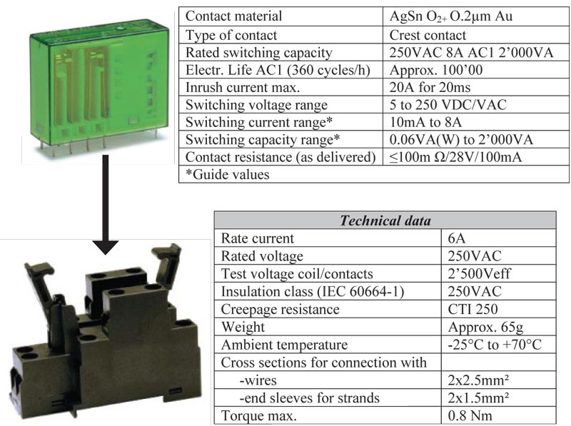
Safety Relay — Part #52-278 (Two Required)
DIN-Rail or Back Plate Mounting
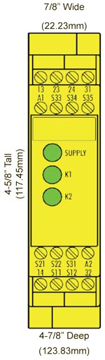
SSSR Safety Relay Interface
Part # SSSR
Allows customer selectable Manual or Auto Reset. Fits in a smaller space than two 52-278 safety relays.
 Basic device for Emergency-Stop and Safety Gate Applications
–Basic device to EN 60204-1:2005 and EN ISO 13849:2007 for single or dual E-stop monitoring.
–PL e / category 4 in accordance with EN ISO 13849-1:2007 (previously EN 954:1997 category 4)
–SILCL 3 in accordance with EN 62061:2005
–Stop category 0 acc. EN 60204-1
–Manual or automatic start
–Cross monitoring
–Feedback loop to monitoring external contactors
–2 Enabling paths, 1 signalling path
–Processing of signals from output switching devices (OSSD) of light curtains acc. EN 61496-1.
–To connect to load side of safety mats acc. EN 1760-1
–Debouncing of inputs
Description of Device and Function
SSSR – This device is a two-channel safety switching device for emergency stop applications
with self-monitoring on each ON-OFF cycle. It conforms to EN 60204-1 and is equipped with positively
driven relays.
Basic function: After supply voltage has been connected to terminals A1/A2 and the safety inputs
closed, operating the reset button closes the enabling current paths (manual start). When the safety
inputs are opened/de-excited the enabling current paths will open.
• Input Power:
Emitter pylon: 24vdc @ .125A
Receiver pylon: 24vdc @ .125A (solid state outputs are PNP which may draw up to .25A additional)
• Internal fuses:
Emitter Pylon: F1 @ 1A
Receiver Pylon: F1 @ 1A, F2 @ 1/2A, F3 @ 1/2A
• Outputs:
Receiver pylon: monitored, 2 outputs, solid state PNP (.5A maxium each output) (24vdc when GREEN, float when RED/off).
Max .25A draw each.
• Optional High Load Safety Relays:
Part Number: 32-108 – 20 AMP, 110 VAC coil with 3 NO (held closed) and 1 NC contact (45mm width, 91mm length, 85mm height)
Part Number: 32-109 – 20 AMP, 24vdc with 3 NO (held closed) and 1 NC contact (45mm width, 91mm length, 115mm height)
• Indicators:
Emitter pylon: Yellow, Red, Green.
Receiver pylon: Yellow, Red, Green.
• Construction:
Painted aluminum extrusion with Acrylic IR lens and Viton Seals providing NEMA 12,13 protection.
Optional Polycarbonate tubes (sleeves) over the pylons provides NEMA 4 protection.
Cables are both 21’ (6.4m) long with a flexible in-line connector 12” (254mm) from the base of each pylon. Maximum 100’ (30.4m)
Emitter pylon: Four conductor 24AWG
Receiver pylon: Six conductor 24AWG
Pylons: Yellow | Cables: Black
• Temperature:
0 to 50c (up to 95% humidity, non-condensing)
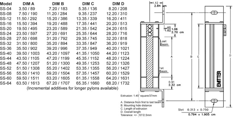
• Dimensions:
1.45” (36.8mm) square X selected length (see tables for lengths)
• Beam Spacing & Minimum Object Sensitivity (MOS)
.5” (12.7mm) .55” (14mm) MOS
1” (25.4mm) 1.18” (30mm) MOS
4” (101.6mm) 4.72” (120mm) MOS
(special order, 4” active area followed by a 4” or 8” gap)
• Response Time and Scanning Frequency:
< 30 mSec total, 10 khz
• Shock:
Tested to withstand high vibration (using shock mounts)
• Self-Checking:
Every 15mSec
• Scanning distance:
From 1’ to 20’ standard (1-6m)
From 21’ to 75’ (6-22.8m) extended range (optional)
The range is stated as a two digit number within the Model #
• Specials:
Custom designed light curtains for special applications. Consult factory.
• Surface Mount Technology
• One Year Warranty
• Made in USA
Pylons with Fixed Mounting Brackets (in/mm)
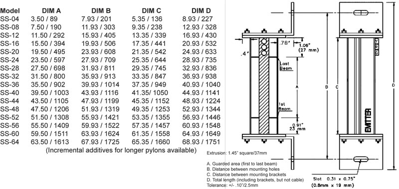
Pylons with Swivel Mounting Brackets (in/mm)
Model SS Output Circuits must be used with either “Control Reliable” PLC Safety Input Circuits or a Safety Relay Module.

Light Curtain Model
SS – Solid State Outputs
Pylon Sizes (Protected Area in inches)
1/2” (13mm) Beam Spacing: 04,08,12,16,20,24,28,32,36,40,44,48,52,56,60,64,68,72,76,80,84,88,92,96,100,104,108,112,116,120
1” (25mm) Beam Spacing: 04,08,12,16,20,24,28,32,36,40,44,48,52,56,60,64,68,72,76,80,84,88,92,96,100,104,108,112,116,120
4” (102mm) Beam Spacing: 20,28,36,44,52,60,68,76,84,92,100,108,116
Customized Blanking Available (consult factory)
Light Curtain Style and Beam Spacing
1/2” (13mm) Spacing of Beams
OF – Constant scan – no blanking.
1F – 1 beam floating blank built-in.
8K – Up to 3 beam floating blank adjustable by the use of a keyswitch removable in all positions. Capable of constant scan or one, two, or three floating beams. (Requires RSD option)
AB – Includes constant scan light curtain, one beam floating blank, and two auto blank modes. (Requires RSD option)
CE – No blanking, 24VDC input power, 2° angle of divergence, and CE certified (designed to conform to the European Market and worldwide IEC 61496 Parts 1 & 2 Standards).
1” ( 25mm) Spacing of Beams
OF1 – Constant scan – no blanking.
1F1 – 1 beam floating blank built-in.
8K1 – Up to 3 beam floating blank adjustable by the use of a keyswitch removable in all positions. Capable of constant scan or one, two, or three floating beams. (Requires RSD option)
AB1 – Includes constant scan light curtain, one beam floating blank, and two auto blank modes. (Requires RSD option)
CE1 – No blanking, 24VDC input power, 2° angle of divergence, and CE certified (designed to conform to the European Market and worldwide IEC 61496 Parts 1 & 2 Standards).
4” ( 102mm) Spacing of Beams (no blanking options available, constant scan only)
OF4 – For perimeter guarding, body detection. 4.25” (108mm) object sensitivity. 4” (102mm) active area followed by a 4” (102mm) gap.
No Additional Charge Options (add underlined suffix to part number)
EDM – External Device Monitoring (EDM): Feature enabled requires the use of 2 external safety relays
LR – Resettable Latching Relays: Requires the light curtain to be manually reset every time the sensing field is penetrated.
Options (Add underlined suffix to part number)
RSD – Model SS Remote Status Display (RSD): Remote mounting plate providing a single location to mount the following on existing panel door: light curtain scrolling diagnostic message display, blanking keyswitch (if applicable), and status indicator lights (all styles).
SMB – Swivel Mounting Brackets for Pylons: Replaces the L-shaped fixed mounting brackets normally supplied. Provides a 360o rotation of pylons.
SSSR – Captive Contact Safety Relay Module
Extended Range Units: 21’ (6.4m) to 75’ (22.8m) scanning distances (specify desired scanning distance).
MPI – Multiple Pylons (two sets) – Cascading or Homerun Cables to the Controller Connected via the CAN Network with one light curtain set area/zone share a common output
MP2 – Multiple Pylons (three sets or more) – Cascading or Homerun Cables to the Controller Connected via the CAN Network with light curtain set two areas/zones with two outputs.
32-109 – High Load Safety Relay – 20 AMP high load safety relay incorporates a 24vdc coil with 3 NO (held closed) and 1 NC contact. Each light curtain requires two relays and EDM feature. Dimensions: (45mm width x 91mm length x 115mm height)
PT – Polycarbonate Tubes: Encase the pylons for high impact protection.
Model SS Output Circuits must be used with either “Control Reliable” PLC Safety Input Circuits or a Safety Relay Module.
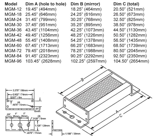
Cornering Mirrors
Through the use of cornering mirrors, multiple sides or work envelopes can be guarded which enhance safety and reduce downtime related to mechanical and electrical interlock systems. Include a 15% reflectivity loss per mirror when calculating the total scanning distance of the light curtain.
Pedestal Dimensions
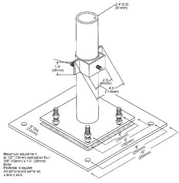 The heavy duty, all welded steel pedestal floor mounts can be used for mounting either light curtain pylons or cornering mirrors. Sliding mounts on the pedestal are of universal design and are supplied standard. Unique floating base on pedestal is designed to compensate for uneven floors.
NOTE: Pedestals must be bolted to the floor, they must not be movable (ANSI B11.19-2010).
1. Sliding mounts supplied
2. Standard height is 72” (1829mm) – Model #8000
Optional 96” (2438mm) – Model #8096
3. Painted OSHA yellow
4. Pedestal is 12 gauge steel
Base Plate is 1/4” (6.35mm) steel plate
Ordering Procedure
Specify Pedestal Model Number and Quantity
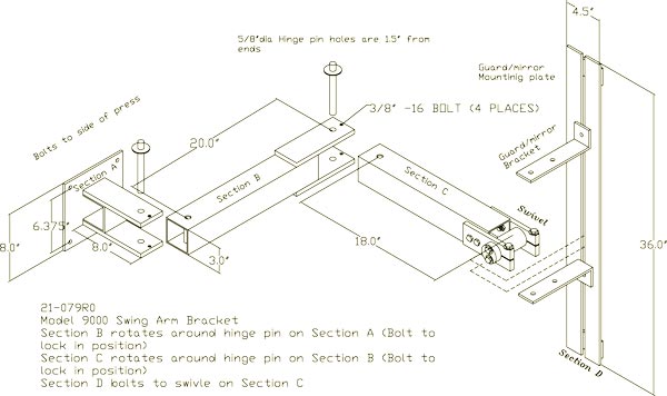
Model 9000 and 9500 Mounting Brackets
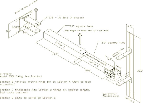
Excellent method of mounting the light guard for press brakes or when the light guard is to be moved for die setups or machine maintenance. Model 9000 consists of three 180-pivot points along with light guard diagonal movement capability for virtually unlimited light guard positioning. Two-inch square tubing 3/16” thick painted OSHA yellow which mounts directly onto the machine housing and makes for a heavy duty yet versatile mounting bracket. Model 9500 consists of two 180-pivot points and one adjustable length arm.
Model 9000
Model 9500
 Part # 11-183: Two piece adjustable mounting bracket for pedestals (with one mounting stud 5/16”-18 stud). Stainless Steel (for Mirror and Guard pylon) (Two required per pedestal) Part # 11-183: Two piece adjustable mounting bracket for pedestals (with one mounting stud 5/16”-18 stud). Stainless Steel (for Mirror and Guard pylon) (Two required per pedestal) |
 Part # 11-184: Two piece adjustable mounting bracket for pedestals (with one mounting stud 5/16”-18 studs 90 degrees apart). Stainless Steel (for Guard at one corner) (Two required per pedestal) Part # 11-184: Two piece adjustable mounting bracket for pedestals (with one mounting stud 5/16”-18 studs 90 degrees apart). Stainless Steel (for Guard at one corner) (Two required per pedestal) |
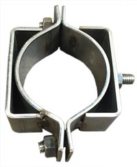 Part # 11-199: Two piece adjustable mounting bracket for pedestals (with two mounting studs 5/16”-18 studs 180 degrees apart). Stainless Steel (for multiple Guards mounted side by side) (Two required per pedestal) Part # 11-199: Two piece adjustable mounting bracket for pedestals (with two mounting studs 5/16”-18 studs 180 degrees apart). Stainless Steel (for multiple Guards mounted side by side) (Two required per pedestal) |
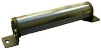 Polycarbonate Tube: Optional Polycarbonate tube which will encase the pylons for high impact protection. Polycarbonate Tube: Optional Polycarbonate tube which will encase the pylons for high impact protection. |
Download Language: English Size: 4.76 MB File Type: PDF
Download Language: English Size: 1.07 MB File Type: PDF