
Safety light curtain Model MG includes a free standing Nema 12 (IP 64) metal box controller and the pylons are rated Nema 4 (IP 65). Input power can be 110V, 220 VAC or 24 VDC. Excellent for free standing enclosure light curtain applications. Complete system diagnostics, mounting brackets and connecting cables supplied standard. Type 4 / Category 4. Made in USA.
 More safety features — fits in tight spaces — continual message display communicates system status — high reliability — meets OSHA, ANSI, CSA, RIA, and CE standards.
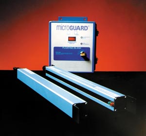
Introducing MicroGuard, the revolutionary new light curtain. MicroGuard is thin in design, fits into tight spaces, uses reliable infrared technology, solid state construction, is easy to install and continually visually communicates the system status with operators and plant personnel.
The MicroGuard advantage is the advanced smart controller design that allows the operator and plant personnel to perform immediate visual checks on the system status. There are 50 diagnostic messages which provide an exact determination of the MicroGuard’s operational status on a continual basis. Messages are easily viewed from the message display on the front of the controller. The operator can verify the condition of operation and status of the system at all times.
For the first time, the MicroGuard’s design allows a quick and easy resolution to system faults and maintenance concerns. Constant communication between the operator and the MicroGuard will save valuable operating time by reducing machine down time. The self-diagnostic capability allows the MicroGuard to trouble-shoot itself by identifying system faults. This constant operating evaluation allows problems to be immediately corrected. This ensures that each MicroGuard user will get maximum machine utilization.
MicroGuard is user friendly. Simple cable hook-ups are used to activate the MicroGuard. Power is common 120VAC, 220VAC, or 24VDC. The thin profile is easily mounted in tight spaces and is available in 30 sizes that can be adapted to any application need. The thin profile pylons feature 1/2” (13mm), 1” (25mm) or 4” (102mm) beam spacing with an easy alignment feature.
Solid state modular NEMA IV (IP 65) construction is easy to maintain with snap-in circuit board construction. Lens covers are high impact plastic and are easily replaced. The redundant circuit and microprocessor design of the MicroGuard ensures safe, uninterrupted operation.
The MicroGuard is also designed for immunity to noise, light, weld flash, and other ambient light sources and is available in either a metal box enclosure or a compact 35mm DIN-rail mountable enclosure.
Diverse Redundancy Design Concept
The safety light curtain Model MG utilizes the diverse redundancy design concept. This gives the safety light system a higher level of redundancy and control reliability. The two microprocessors are of different design, and the microprocessor or parallel programs are run and made up from different instruction sets written by different programmers.
Self-Checking Circuitry
The safety light curtain Model MG self-checks every 20 milliseconds. Self-checking is the ability to electronically verify that all of the systems’ critical internal circuit components and their redundant counterparts or back-ups are operating properly.
Extra Safe Design
Provides two methods of cross monitoring design. One utilizes two microprocessors and two captive contact relays and the other uses four watchdog timers monitoring the system and the captive contact relays.
Redundant Captive Contact Safety Relays
Redundant relays assure safety if an output relay should fail. The MicroGuard utilizes safety relays which have force-guided contacts. This is a configuration where the contacts are mechanically locked together so that if one set of contacts weld, the other contacts cannot change state. If one should fail, code “Relay Fault” will be displayed on the diagnostic message display. The complete guarding system consists of two miniature pylons with a controller for system diagnostics and wiring interface.
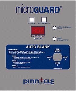
External Diagnostic Message Display
Standard on the safety light curtain Model MG is the “External Diagnostic Display.”
Alphanumeric Plain English Messages
Scrolling message display shows status and fault codes of the unit. This is an excellent safety and maintenance feature which is unparalleled in the machine guarding industry for enhancing machine utilization.
Control Reliable System
Critical components of the MicroGuard are duplicated so that a single component failure will not cause an unsafe condition. If a component does fail, the units’ self-checking circuitry recognizes the situation and initiates a safe stop of the machine. The fault is then displayed on the message display.
Powerful Infrared Light Source
The safety light curtain Model MG utilizes powerful, safe, and predictable infrared light as its sensing source. This gives the system greater reliability and enhances machine utilization by minimizing nuisance trips and shutdowns caused by dirt, coolants, lubrication mists, and machine oils. The MicroGuard is highly immune to EMI, RFI, and ambient light conditions and are unaffected by strobe lights and weld flash generated light sources.
Extensive Testing
The safety light curtain Model MG incorporates extensive testing and burn-in to establish a high degree of product reliability and safety.
 MicroGuard Controller Unique Features
–Same controller for all size light curtains: 4” (102mm) to 120” (3048mm)
–Same controller for various input ranges: 24VDC, 120VAC, 220VAC
–Message display (external) – Bright red LED alphanumeric scrolling message display
–50 plain English diagnostic and operating status messages
–Counts and displays location of obstructed beams
–Counts and displays number of obstructed beams
–System diagnostics with display to aid in-field maintenance
–Blanking functions controlled by keyed selector switch on front panel with display and indicator
–Smart controller eliminates cumbersome troubleshooting techniques
–Control reliable system
–Internal mute-out system (optional)
Smart Controller
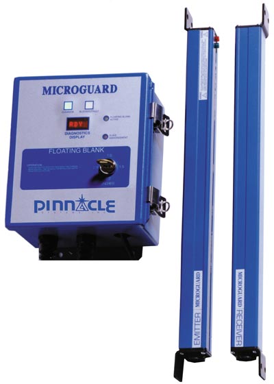
The Smart MicroGuard Controller makes machine guarding safer, easier to use, and enhances machine utilization measurably. It is unique in the machine guarding industry for the ability to constantly display the operating conditions of the safety light curtain. The Controller informs the user of any faults, failures, and the current operating status of the safety system in plain English on the external message display center. The message display is located on the front panel of the Controller (shown left). This gives the machine operator and front line supervisor access to information quickly and safely.
 The MicroGuard Controller diagnostics message display will show all faults related to redundant circuitry, microprocessors, captive contact safety relays, bad grounds, external infrared sources, shorts, blanking functions, etc. The Controller will also display the locations of misaligned or obstructed beams and then count and display how many beams have been obstructed. Additionally, if a printed circuit board or component should fail, the faulty board and beam number will be shown on the display. The board then can be replaced quickly in the field, eliminating costly downtime.
The counting and displaying the number of beams blanked out is required information when determining the depth penetration factor for proper installation of any light curtain.
ANSI B11.19-2010.
Output Circuitry
Safety Output Configuration
Every MicroGuard comes standard with two Captive Contact Safety Relays, auxiliary relay, and fault relay. The metal box controller can be configured for a “Single Stop” circuit or a “Dual Stop” circuit output.
Single Stop Circuit SS – Both internal Safety Relays are wired in series and the user is provided with one dry contact output. (Open when fault or blocked.) Supplied standard on the safety light curtain Model MG.
Dual Stop Circuit DS – Each internal Safety Relay is wired separately which provides the end-user with two separate dry contact outputs. (Both open when fault or blocked.) Add suffix DS to Metal Box (MG) part number.
The DIN-rail controller comes configured for a Dual Stop circuit with a jumper wire between outputs so that the user can wire into a Single Stop circuit system provided they wire both Safety Relays in series.
WARNING – Both safety relays in the dual stop configuration must be wired into the machine isolated stop circuits of the machine control.
Metal Box Controller Module Standard Provisions—designed to facilitate any guarding system interface and monitoring desired. Usage is optional.
CINCINNATI INTERFACE-with Red LED Indicator or EMERGENCY STOP INPUT (optional)
DESCRIPTION: The Cincinnati Interface is provided to allow an external device to determine if the light curtain is still capable of shutting down the safety control circuit. The Cincinnati Interface allows an external device to override the light curtain and initiate a RED condition and open up the standard output relay contacts.
APPLICATION: Cincinnati Press, PLC
EXTERNAL RELAY CHECK-with Green LED Indicator
DESCRIPTION: The External Relay Check allows the MicroGuard to monitor a pair of external relays in series using the external relays secondary set of DRY contacts, provided that they are N.C. force-guided contacts. The captive or force-guided contacts will maintain the identical positions as the primary set of contacts on the external relays, except that the secondary set of contacts are wired to signal the reverse of the primary (i.e., primary are N.O. and secondary are N.C.). The circuit looks for both closing and opening of the external relay contacts. The MicroGuard system is a safe external relay check.
APPLICATION: Monitoring external relay contacts for shorts or opens.
EXTERNAL VOLTAGE CHECK PROVISION-with Green LED indicator
DESCRIPTION: The External Voltage Check allows for the MicroGuard to monitor voltage coming from any outside source as a condition for keeping the light curtain green. This option is very similar to the External Relay Check except that this operates with high voltage so that it can be used to monitor other devices besides relay contacts.
APPLICATION: Monitor voltage at a solenoid, relay, etc.
AUXILIARY OUTPUT CONTACT PROVISIONS
DESCRIPTION: The Auxiliary Output Contact provides both an N.O. and N.C. isolated (DRY) contact output to signal the condition of the light curtain. The output is used in conjunction with the standard pair of output relays that are wired to the safety circuit of the equipment.
APPLICATION: Signal to PLC, etc.
DATA INPUT/OUTPUT FOR USE WITH REMOTE PLC (optional)
DESCRIPTION: This option allows the user to specify up to four signal lines as either input and/or output lines for issuing remote commands to the MicroGuard and/or sending commands to a PLC.
APPLICATION: Use this option if you need to know object size or to use your PLC to program Auto-Blank, Floating-Blank, reset “Penetration,” adjust guarded area, etc. This option is programmed at the factory for the user and is individually customized.
 ● The safety light curtain Model MG meets or exceeds OSHA, ANSI, CSA, RIA, CE standards, UL Subject 491, UL1998, IEC 61496 standard parts 1 and 2, ISO 13849 1 &2, Safety Category 4 (EN 954-1)
● Total system diagnostics and display for component and board level assemblies
● Two sets of operator status indicators
● Modular design for easy in-field maintenance
● Self-checking circuitry
● Fault relay output built-in
● Lockable controller box – NEMA 12 & 13 (IP 64)
● Easy access for wiring
● Push button reset with memory
● High immunity to strobe type and weld flash generated light
● Miniature design
● Extended scanning ranges available for the safety light curtain Model MG
● Replaceable infrared lens cover on pylons
● High immunity to EMI and RFI noise sources
● Interfaces easily with all types of machine controllers and PLC’s
● Dual independent channel microprocessor design
● Single/multiple floating beam blanking with indicator
● Single/multiple fixed beam blanking with indicator
● Auto blanking feature with indicator
● Built-in machine interface monitoring
● Dual self-checking captive contact safety relays
● Non-mated units, matched sets are not required
● 2-, 3-, 4-, or 5-sided protection available with mirrors
● 30 standard sizes available: 4” (102mm) to 120” (3048mm) lengths in 4” (102mm) increments
● Easy to align and install
● In-field maintenance
● Multi-lingual diagnostic display available with the safety light curtain Model MG
● Two-year warranty on the safety light curtain Model MG
● Single controller for multiple light curtains (up to four sets)
● The safety light curtain Model MG is Made in the USA

Complete system monitoring on DeviceNet fieldbus networks. The MicroGuard controller family is fully compatible with the DeviceNet fieldbus and can be connected directly into the fieldbus for non-safety monitoring of system status. DeviceNet is the leading low-cost communications link that connects a wide range of automated manufacturing devices for greater usability and convenience. Multiple MicroGuard controllers can be networked with numerous other devices on a single DeviceNet network. Add suffix DN to controller part number for this optional feature.
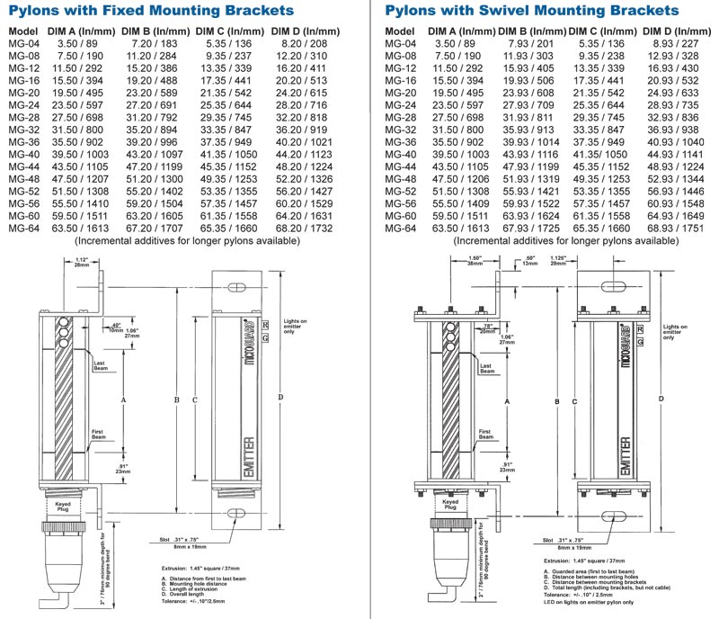
Pylons:
• Heavy duty aluminum extrusion NEMA IV (IP 65)
• Replaceable infrared lens cover (acrylic)
• Sealed bulkhead positive locking circular connectors
• Mounting brackets supplied standard
• Emitter pylon – red/green/yellow status indicators
Cables:
• Shielded PVC 22 AWG cables with quick disconnects and strain relief fittings
• Emitter cable – 20’ (6.1m) supplied standard for the Metal Box Controller Module and 22’ (6.7m) supplied standard for the DIN-rail Controller Module
• Receiver cable – 8’ (2.44m) supplied standard for the Metal Box Controller Module and 22’ (6.7m) supplied standard for the DIN-rail Controller Module
• External Alphanumeric Diagnostic & Status Message Display
• Infrared Light Source: Solid state light emitting diodes
• Beam Spacing: 1/2” (13mm) or 1” (25mm)
• Minimum Object Sensitivity:
1/2” (13mm) beam spacing is .55” (14mm)
1” (25mm) beam spacing is 1.18” (30mm)
• Response Time: < 30 milliseconds (all sizes)
• Scanning Frequency: 5.9 Khz
• Temperature Range: 32o to 120o F (0o -51o C)
• Shock tested to withstand high vibration applications per UL991
• Self-Checking every 20 milliseconds
• Scanning Distance: The safety light curtain Model MG is supplied standard with a 20’ (6.1m) scanning capability. Extended range units are available, consult your representative or the factory. Scanning distances must be specified—75’ (22.8m) maximum.
• Complete Guarding System Supplied: Transmitter and receiver pylons, controller, mounting brackets, connectors and cables, installation and operation manual.
• CSA Approved, UL Listed, and CE Certified
• Two-Year Warranty
• Patented #5,243,183
• Safety Category 4 (EN 954-1 and IEC 61496 Part 1 and Part 2 or EN 61496)
• SIL 3 (EN 61508)
• Performance Level PL e (ISO 13849-1)
• DeviceNetTM Fieldbus Network Compatible (optional)
• Input Power:
18 to 35VDC @ 10W
90 to 140VAC @ 12VA Standard
140 to 220VAC @ 12VA
All AC voltages work with 50 or 60 Hz
• Power Consumption: 11 watts total
• Output Circuit: Two captive contact self-checking safety relays
• Relay Contact Rating: Rated at 8 AMPS @ 250VAC resistive
• Auxiliary Output Contact: Rated at 8 AMPS @ 250VAC resistive
• Fuses:
AC power: 1 AMP SLOW BLOW
DC power: 1 AMP FAST BLOW
External Voltage Check: 5 AMP FAST BLOW
• Fault Output Relay: Isolated output for faults
• Metal Box Indicators:
External:
OK/CLEAR Green LED
BLOCK/FAULT Red LED
AUTO/FLOAT ACTIVE Yellow LED
SLAVE DISAGREEMENT Red LED
DIAGNOSTICS DISPLAY Alphanumeric scrolling message display
Internal:
+ 12V Red LED
Cincinnati Interface Red LED
+ 5V Yellow LED
External Relay Green LED
+ 5V Yellow LED
External Voltage Green LED
– 5V Green LED
• Diagnostic Message Display: English or Spanish available. Customized languages are also available, consult factory.
• Push Button Reset with Memory
• Enclosure: All 18 gauge painted steel NEMA 12 (IP 64) lockable box with sealed front panel and sealed cable entry fittings (8 lbs.)
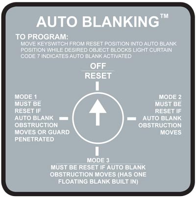 Auto-Blanking – (AB) Option
The advanced “Auto Blank” option is unique because it will automatically blank out only the required number of beams needed to accept an obstruction such as a conveyor, bracket, or fixture. The unit is easily programmed by a supervisory controlled four-position keyed selector switch located on the front panel of the MicroGuard Controller (shown left). The “Auto Blank” method of blanking is much safer than DIP switch or master/slave blanking systems because only the areas of the obstruction will be blanked. This feature prohibits unsafe oversizing of the blanked area commonly found throughout the industry on manually blanked systems. “Auto Blank” also eliminates the need to count beams and to locate where and what beams are to be shut off to obtain the correct beam elevation to accept an obstruction. This information is displayed on the message display of the controller. “Auto Blank” will also watch the obstruction and, if it moves or is removed, will go into a “machine stop mode” to prevent further machine operation. This is an additional safety feature not available on manually blanked units. These features truly enhance production while providing the ultimate in safety.
When the key switch is turned to the “Auto Blank” function, the “External Diagnostic Message Display” will show the number of blocked beams and where the obstruction is in the light curtain, then verify that the obstruction is being monitored. This is required information for the depth penetration factor and for proper installation of any safety light curtain.
The versatile “Auto Blank” (AB) blanking series includes:
Constant scan light curtain
One beam floating blank built-in plus “Auto Blank” capability
Two “Auto Blank” modes – up to 4” blanked out (larger sizes available upon request) but need not be sequential
A. One “Auto Blank” mode with keyed reset when guarded zone is penetrated
B. One “Auto Blank” mode with automatic reset when guarded zone is penetrated
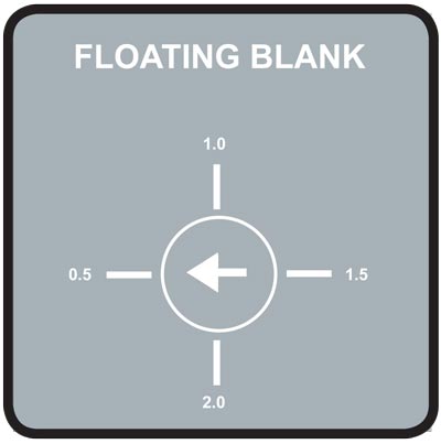 Floating Blank – (8K) Option
The “Floating Blank” option provides the flexibility necessary to effectively guard all types of equipment that require multiple floating beams. This is quite common in the fabricating industry where the work piece moves.
The “Floating Blank” permits work pieces to be formed vertically or horizontally through the guarded area without shutting down the machine. Entry into the protected area by the operator or passerby will prevent the start or, if the machine is in motion, will provide a signal to stop the machine.
The “Floating Blank” is controlled by a keyed selector switch that will allow a work opening of 2” (51mm) based on 1/2” (13mm) increments (shown left). This information is displayed on the message display of the controller. Blanking adjustments required when die heights change are not necessary. The “Floating Blank” light curtain automatically adjusts to the various feed positions providing production with protection.
The “Floating Blank” (8K) Option includes:
1/2” (13mm) – Constant scan light curtain
1” (25mm) – One floating beam
1-1/2” (38mm) – Two floating beams
2” (51mm) – Three floating beams
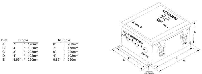
Metal Box Controller Module
For multiple light curtain controllers, the Emitter pylons are plugged into the top of the enclosure and the Receivers are plugged into the bottom as shown. The holes on the top of the box are mirror images of the bottom holes. For single light curtain controllers, the Emitter and Receiver pylons are both plugged into the bottom as shown.
Tol. +/- 0.10 inches / 2.54 mm
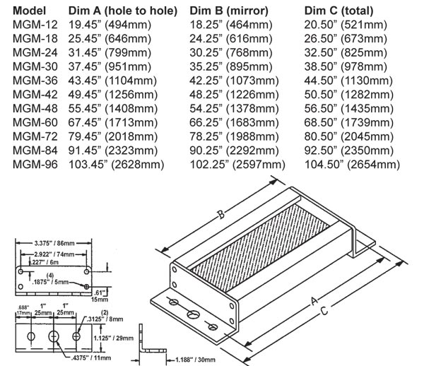
Cornering Mirrors
Through the use of cornering mirrors, multiple sides or work envelopes can be guarded which enhance safety and reduce downtime related to mechanical and electrical interlock systems. Include a 15% reflectivity loss per mirror when calculating the total scanning distance of the light curtain.
Pedestal Dimensions
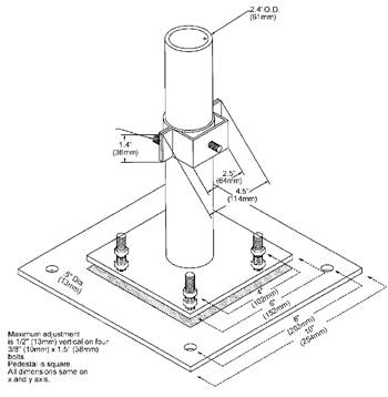 The heavy duty, all welded steel pedestal floor mounts can be used for mounting either light curtain pylons or cornering mirrors. Sliding mounts on the pedestal are of universal design and are supplied standard. Unique floating base on pedestal is designed to compensate for uneven floors.
NOTE: Pedestals must be bolted to the floor, they must not be movable (ANSI B11.19-2010).
1. Sliding mounts supplied
2. Standard height is 72” (1829mm) – Model #8000
Optional 96” (2438mm) – Model #8096
3. Painted OSHA yellow
4. Pedestal is 12 gauge steel
Base Plate is 1/4” (6.35mm) steel plate
Ordering Procedure
Specify Pedestal Model Number and Quantity
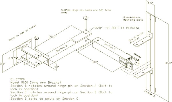
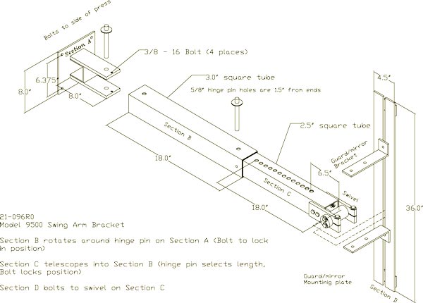
Model 9000 and 9500 Mounting Brackets
Excellent method of mounting the light guard for press brakes or when the light guard is to be moved for die setups or machine maintenance. Model 9000 consists of three 180-pivot points along with light guard diagonal movement capability for virtually unlimited light guard positioning. Two-inch square tubing 3/16” thick painted OSHA yellow which mounts directly onto the machine housing and makes for a heavy duty yet versatile mounting bracket. Model 9500 consists of two 180-pivot points and one adjustable length arm.
Model 9000
Model 9500
 Part # 11-183: Two piece adjustable mounting bracket for pedestals (with one mounting stud 5/16”-18 stud). Stainless Steel (for Mirror and Guard pylon) (Two required per pedestal) Part # 11-183: Two piece adjustable mounting bracket for pedestals (with one mounting stud 5/16”-18 stud). Stainless Steel (for Mirror and Guard pylon) (Two required per pedestal) |
 Part # 11-184: Two piece adjustable mounting bracket for pedestals (with one mounting stud 5/16”-18 studs 90 degrees apart). Stainless Steel (for Guard at one corner) (Two required per pedestal) Part # 11-184: Two piece adjustable mounting bracket for pedestals (with one mounting stud 5/16”-18 studs 90 degrees apart). Stainless Steel (for Guard at one corner) (Two required per pedestal) |
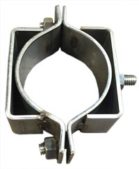 Part # 11-199: Two piece adjustable mounting bracket for pedestals (with two mounting studs 5/16”-18 studs 180 degrees apart). Stainless Steel (for multiple Guards mounted side by side) (Two required per pedestal) Part # 11-199: Two piece adjustable mounting bracket for pedestals (with two mounting studs 5/16”-18 studs 180 degrees apart). Stainless Steel (for multiple Guards mounted side by side) (Two required per pedestal) |
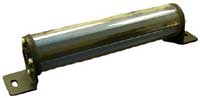 Polycarbonate Tube: Optional Polycarbonate tube which will encase the pylons for high impact protection. Polycarbonate Tube: Optional Polycarbonate tube which will encase the pylons for high impact protection. |
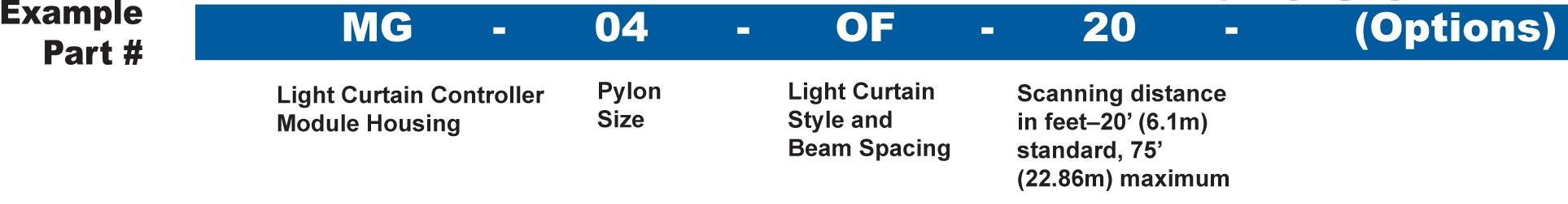
Safety Light Curtain Model MG Ordering Procedure
Light Curtain Controller Module Housing
MG – NEMA 12 & 13 (IP 64) stand alone Metal Box Controller Module
Pylon Sizes (Protected Area)
1/2” (13mm) Beam Spacing: 04,08,12,16,20,24,28,32,36,40,44,48,52,56,60,64 68,72,76,80,84,88,92,96,100,104,108,112,116,120
1” (25mm) Beam Spacing: 04,08,12,16,20,24,28,32,36,40,44,48,52,56,60,64,68,72,76,80,84,88,92,96,100,104,108,112,116,120
4” (102mm) Beam Spacing: 20,28,36,44,52,60,68,76,84,92,100,108,116
Customized Blanking Available (consult factory)
Safety Light Curtain Model MG Style and Beam Spacing
1/2” (13mm) Spacing of Beams
OF – Constant scan – no blanking.
1F – 1 beam floating blank built-in.
8K – Up to 3 beam floating blank adjustable by the use of a keyswitch removable in all positions. Capable of constant scan or one, two, or three floating beams.
AB – Includes constant scan light curtain, one beam floating blank, and two auto blank modes.
CE – No blanking, 24VDC input power, 2° angle of divergence, and CE certified (designed to conform to the European Market and worldwide IEC 61496 Parts 1 & 2 Standards).
1” ( 25mm) Spacing of Beams
OF1 – Constant scan – no blanking.
1F1 – 1 beam floating blank built-in.
8K1 – Up to 3 beam floating blank adjustable by the use of a keyswitch removable in all positions. Capable of constant scan or one, two, or three floating beams.
AB1 – Includes constant scan light curtain, one beam floating blank, and two auto blank modes.
CE1 – No blanking, 24VDC input power, 2° angle of divergence, and CE certified (designed to conform to the European Market and worldwide IEC 61496 Parts 1 & 2 Standards).
4” ( 102mm) Spacing of Beams (no blanking options available, constant scan only)
OF4 – For perimeter guarding, body detection. 4.25” (108mm) object sensitivity. 4” (102mm) active area followed by a 4” (102mm) gap.
Options (Add underlined suffix to part number)
SMB – Swivel Mounting Brackets for Pylons: Replaces the fixed mounting brackets normally supplied. Provides a 360o rotation of pylons.
MO – Guarding Mute-Out: Mutes out the light curtain during the non-hazardous portion of the machine cycle.
32-108 – High Load Safety Relay – 110 VAC – 20 AMP high load safety relay incorporates a 110 VAC coil with 3 NO (held closed) and 1 NC contact. Each light curtain requires two relays. Dimensions: (45mm width x 91mm length x 85mm height)
32-109 – High Load Safety Relay – 24vdc – 20 AMP high load safety relay incorporates a 24vdc coil with 3 NO (held closed) and 1 NC contact. Each light
curtain requires two relays and EDM feature. Dimensions: (45mm width x 91mm length x 115mm height)
DN – DeviceNetTM: Fieldbus network compatible.
Extended Range Units: 21’ (6.4m) to 75’ (24.8m) scanning distances (specify desired scanning distance).
LR – Resettable Latching Relays: Requires the light curtain to be manually reset every time the sensing field is penetrated (built-in standard on the DIN-rail Controller Module).
SC – Single Controller for Multiple Light Curtains: Cost effective approach when a machine requires multiple light curtains. All curtains are controlled by a single MicroGuard controller. Up to four sets of pylons can be connected to the controller.
ES – Emergency Stop Input: E-Stop input requiring the MicroGuard to issue a stop command (built-in standard on the DIN-rail Controller Module).
24VDC – 24VDC Input Power: Required for 24VDC input power.
220VAC – 220VAC Input Power: Required for 220VAC input power.
ETH – Ethernet Connectivity
Extra Pylon Protection (Optional)
PT – Polycarbonate tube which will encase the pylons for high impact protection.